Types of Lines and Their Importance in Technical Drawing
📑 10 slides
👁 29 views
📅 1/31/2026
Introduction to Technical Drawing Lines
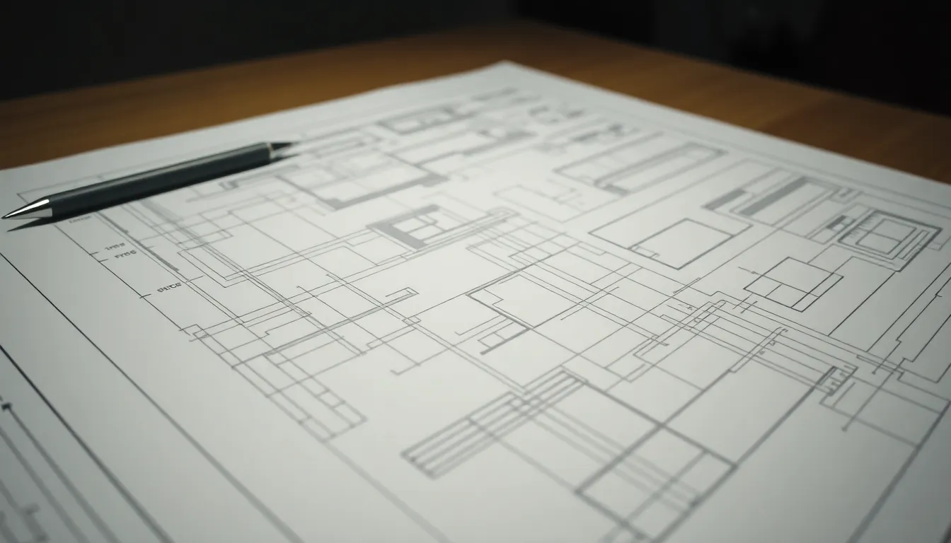
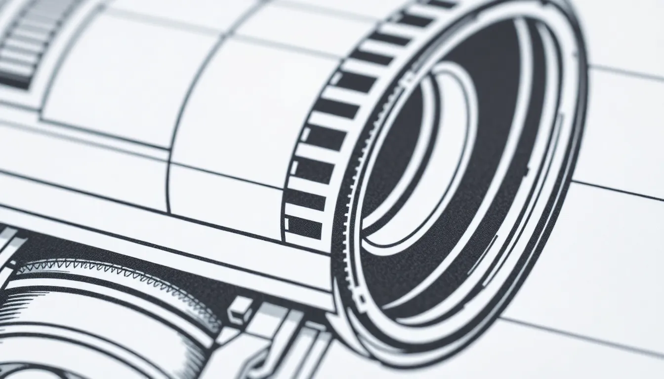
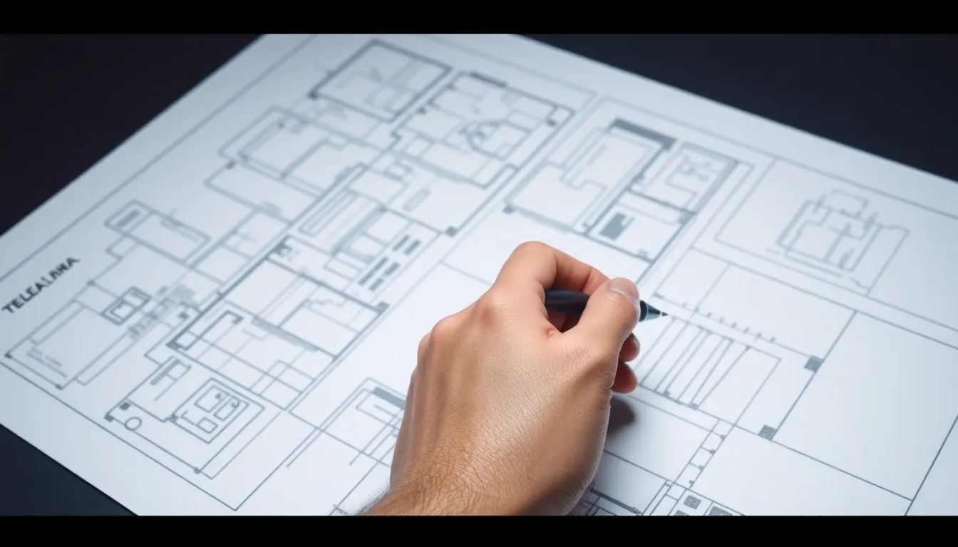
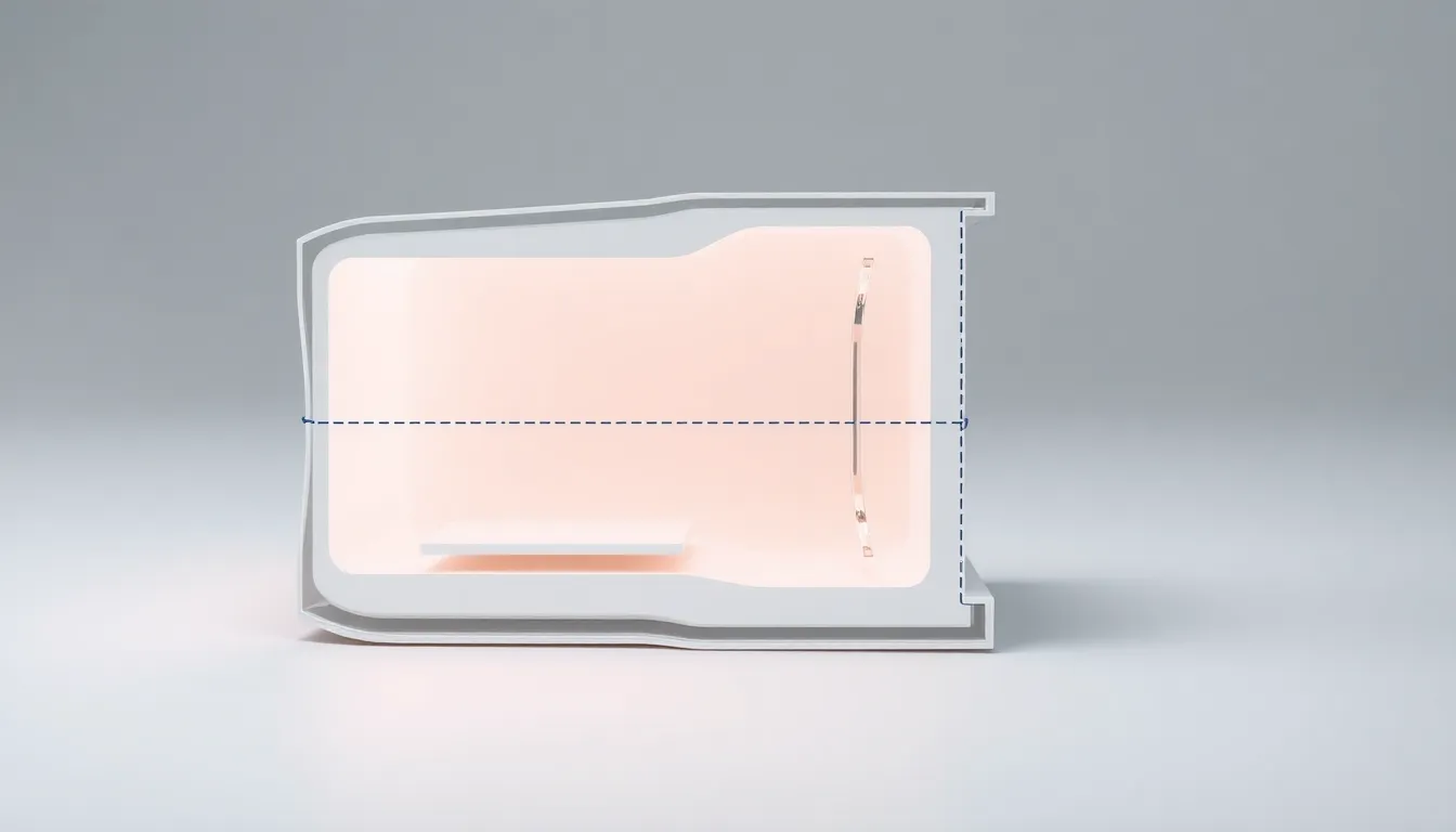
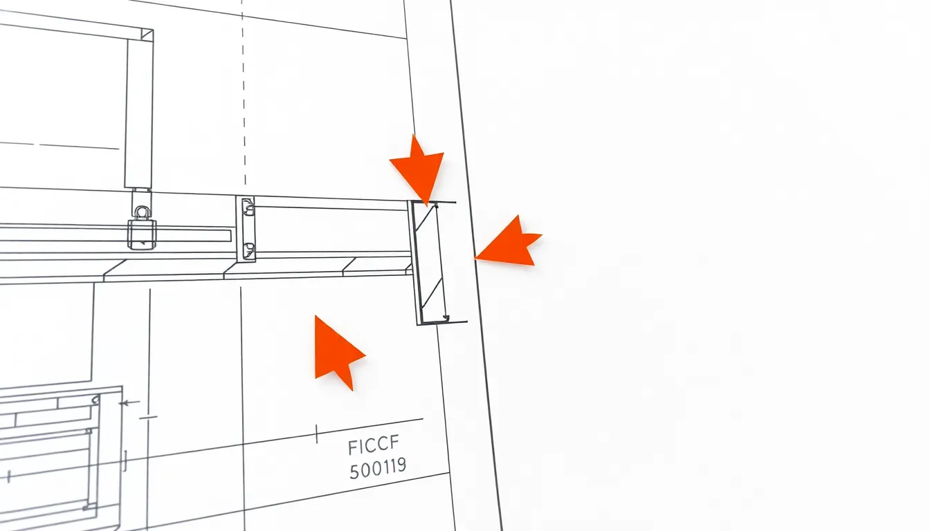
Technical drawing relies on precise lines to communicate design intent.
2
Continuous Thick Lines
- Used for visible outlines and edges of objects.
- Typically 0.5-0.7mm thick to stand out clearly.
- Essential for defining the main shape of components.
3
Continuous Thin Lines
- Applied for dimensions, extensions, and hatching.
- Usually 0.18-0.25mm thick for secondary details.
- Helps maintain drawing clarity without overwhelming.
4
Dashed Lines
- Represent hidden edges and features not visible in view.
- Dashes are typically 3-4mm long with 1mm gaps.
- Critical for showing internal structures and assemblies.
5
Chain Lines
- Indicate center lines, symmetry, or pitch circles.
- Alternate long and short dashes (10mm and 2mm).
- Vital for alignment and rotational part features.
6
Zigzag Lines
- Used for long breaks in uniform sections.
- Saves space by shortening repetitive objects.
- Common in shaft, rod, and piping drawings.
7
Phantom Lines
- Show alternate positions or moving parts.
- Composed of one long and two short dashes.
- Important for demonstrating mechanisms in motion.
8
Cutting Plane Lines
- Indicate where sectional views are taken.
- Thick lines with arrowheads showing direction.
- Crucial for understanding internal geometries.
9
Stitch Lines
- Represent sewing or stitching in product design.
- Series of small dashes with consistent spacing.
- Used extensively in fashion and upholstery drawings.
10
Conclusion: Line Importance
- Correct line usage conveys precise technical information.
- Standardized line types enable global understanding.
- Mastery of lines reduces errors and improves communication.
1 / 10